
You’ll start by isolating the hydrostatic drive and securing the chassis on jack stands—neglect this, and you’re risking shearing force on the axle seal. The real complexity lies ahead: bead seating requires controlled psi application, and improper mounting geometry guarantees rotational vibration. You haven’t encountered the strap-and-inflate method’s critical failure points yet.
Position Your Riding Mower on Solid Ground
Where exactly should you position the riding mower before commencing tire service? You’ll maneuver the unit onto a flat surface, ensuring grade variance doesn’t exceed 0.5 percent lateral inclination. Engage the parking brake mechanism fully; you’re locking the transmission to prevent unintended longitudinal displacement. You’ll position wheel chocks—preferably rubber or urethane compound—at the opposing axle’s wheels, creating mechanical blocking against rollback.
You’ve initiated the foundational protocol for riding mower tire service. You’re establishing static equilibrium prior to any elevation procedures. Remove the ignition key or disconnect the spark plug lead wire—you’re eliminating ignition system energization hazards. Clear the service envelope of personnel; you’re mitigating struck-by and caught-between injury vectors. Verify surface integrity beneath anticipated jack stand placement points; you’re preempting subsurface failure during subsequent wheel removal operations. Your preparatory phase ensures adequate safety margins before load transfer occurs.
Jack up the Mower and Secure It With Stands
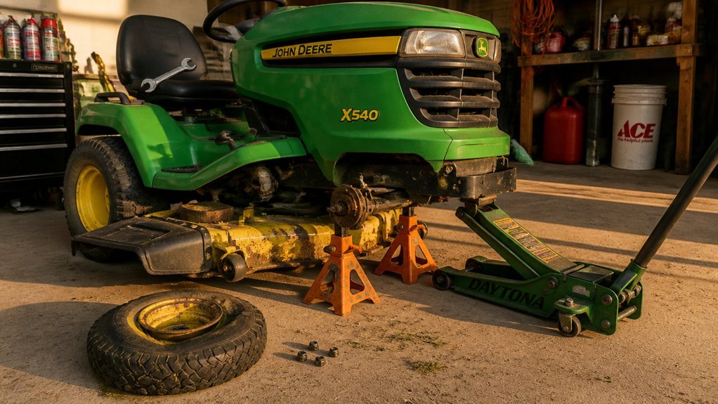
You’re now ready to transfer the mower’s mass from its suspension to your lifting equipment. Position your floor jack beneath a solid frame point—never the deck—to raise the side containing the target tire. Lift until the wheel clears the ground sufficiently for removal clearance.
Once elevated, slide jack stands under the frame, ensuring they’re squarely contacting load-bearing structural members. Lower the jack slowly, transferring the full static load onto the stands. Before proceeding, chock the opposite wheel to prevent translational movement. Verify tri-pod stability by applying lateral force to the chassis—any deflection indicates inadequate mounting.
Re-check stand positioning and ground contact integrity. Only when you’ve confirmed zero dynamic instability should you consider the tire accessible for service. Your mechanical isolation is now complete.
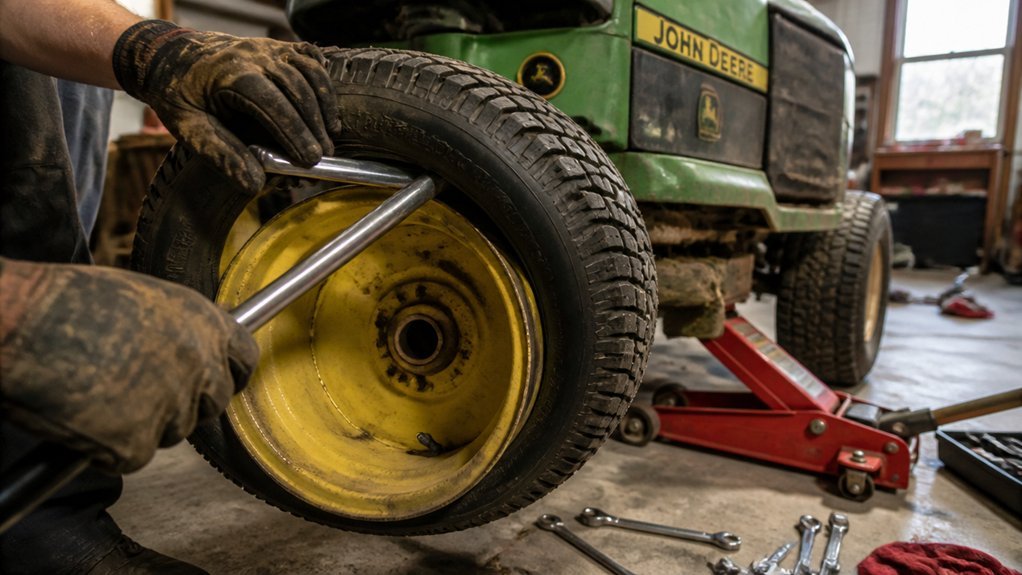
Remove the Old Wheel From the Axle
Why begin with the cap? The debris cap protects the axle’s retaining hardware from particulate accumulation. Pry it off to expose the cotter pin or E-clip securing your old wheel to the axle shaft.
Grasp needle-nose pliers and extract the retaining pin or E-clip. Don’t scatter the washers—maintain their axial sequence for proper preload during reassembly. Set them aside in order.
Now execute wheel removal. If the wheel hub binds, you’ll need to deflate tire pressure further before proceeding. Once liberated from retaining hardware and spacers, slide the assembly off the axle. Should residual friction persist, employ tire pry tools at the rim interface, ensuring complete deflation before manipulating the bead. Document washer placement meticulously.
Deflate and Break the Tire Bead
With the wheel assembly removed and the hub exposed, you’re ready to address the tire itself. You’ll deflate and break the tire bead systematically to prevent snap-back and rim damage. Begin with valve stem release: extract the valve core using a valve-core tool or depress the pin, ensuring complete depressurization. Fully deflated, the sidewall loses structural rigidity, reducing resistance during separation.
Apply tire mounting lubricant or soapy water solution to the bead seating interface; this reduces friction and facilitates subsequent manipulation. Generate bead-breaking leverage using pry bars or large screwdrivers inserted between the tire bead and rim flange. Work circumferentially, alternating pressure points to distribute load and avoid localized stress concentrations. Maintain gradual, even force until the bead unseats completely from both rim flanges, enabling tire removal.
Mount the New Tire Onto the Rim
How should one approach mounting without compromising structural integrity? You’ll begin with the deflated tire to reduce mechanical stress during the mounting tire sequence. Verify rim compatibility before proceeding; mismatched bead seat diameters guarantee failure. Apply bead lubricant—soapy water suffices—to the tire’s inner circumference and rim edge. This reduces friction coefficient during manipulation. You’ll knead the tire onto the rim using body weight distributed across the sidewall, leveraging a tire iron or bead tool to incrementally advance the bead over the flange without gouging the rim surface. Work circumferentially, alternating sides to prevent asymmetrical loading. Once positioned, you’ll inflate gradually, monitoring bead seating uniformity around the entire rim circumference. Finalize by confirming the bead exhibits consistent circumferential engagement and no visible distortion exists.
Seat the Bead With the Strap-And-Inflate Method
What happens when bead seating proves recalcitrant under standard inflation? You deploy the strap-and-inflate method. Begin tire mounting with the assembly deflated. Loop a heavy clamp strap around the tread circumference, applying lateral compressive force to press the bead against the rim flange. Inflate incrementally, pausing to inspect bead seating symmetry and edge alignment. Adjust strap tension dynamically as the casing expands. Ensure rim surfaces and bead toes are contaminant-free; apply soapy water lubricant to reduce friction coefficient during engagement. The strap maintains uniform pressure distribution, preventing asymmetric displacement. Once the bead seats audibly and the tire wall sits flush concentrically, cease inflation. Remove the strap only after achieving full bead lock, completing this phase of tire mounting.
Inflate to Manufacturer PSI Specs
Where should you direct your attention once bead seating’s achieved? You’ll locate the manufacturer-molded PSI specification on the tire’s sidewall, then execute inflation to that precise metric using an air compressor equipped with an integrated pressure gauge. You’ll monitor tire pressure incrementally during this phase, safeguarding against over-inflation that risks catastrophic bead damage. Post-inflation, you’ll recheck PSI cold—thermal expansion from ambient heat or operational friction skews readings.
You’ll identify under-inflation through sidewall bulging or incomplete bead seating; you’ll correct deviations via controlled deflation or gradual PSI augmentation. You’ll institutionalize tire pressure logging as protocol within your mower maintenance regimen, verifying specifications prior to each operational cycle to preserve traction integrity and mechanical efficiency. Precision inflation directly correlates with prolonged service life and optimized cutting performance.
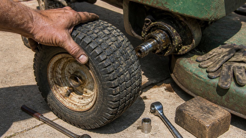
Reinstall the Wheel on Your Riding Mower
With the tire bead fully seated and PSI calibrated to manufacturer specifications, you’re now positioned to remount the wheel assembly onto the mower chassis.
Initiate wheel installation by engaging axle alignment procedures. Manipulate the riding mower tire until the wheel splines interface precisely with the wheel shaft, verifying key stock insertion to preclude rotational slippage. You’ll secure mechanical integrity by reapplying washers in their original stacking sequence and orientation, torquing the retaining hardware to OEM specifications. Complete the assembly by reseating the debris cap onto the wheel shaft terminus, establishing a protective barrier against particulate infiltration and moisture ingress. This component shields critical hub internals from environmental degradation. Confirm all fasteners achieve proper clamp load before proceeding.
Lower the Mower and Test Drive
How precisely does one shift from elevated maintenance configuration to operational status without compromising structural integrity?
You’ll remove the jack stands and actuate the hydraulic release mechanism, executing controlled descent until the tire change interface contacts firm substrate. Reconnect all disengaged driveline components, verifying washer-stack sequencing matches OE specifications. You’ll reinstall the debris cap, ensuring the wheel shaft cap achieves proper interference fit to maintain ingress protection ratings.
Now, initiate a test drive protocol on a planar, obstruction-free surface. You’ll evaluate steering responsiveness, chassis balance, and deceleration metrics while monitoring for anomalous oscillations. If the riding mower exhibits wobble or acoustic irregularities, you’ll immediately suspend operation and recheck bead seating integrity, tire inflation PSI, and wheel mounting concentricity before resuming operational duty cycles.
Conclusion
You’ve executed the complete tire replacement protocol—bead seating verified, fasteners torqued to OEM spec, and inflation pressure validated. Reinspect concentricity and fastener torque after initial operation. Maintain periodic pressure monitoring and tread inspection to optimize service life. Your riding mower’s driveline integrity depends on proper wheel assembly maintenance. Resume cutting operations with confidence in your mechanical remediation.